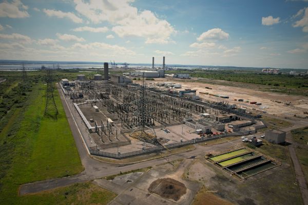

Project Snapshot
Client: UK Renewable Energy Developer – Onshore Wind Farm
Location: UK
Services: Transformer Energisation Study & P28 Grid Compliance Study
Date: March 2026

A UK onshore wind project required an energisation strategy for a 132/33 kV, 60 MVA grid transformer and associated wind turbine transformers before commissioning. The client sought assurance that energising the transformer would not introduce unacceptable voltage disturbance on the connected network at the 132 kV connection point.

The Engineering Challenge
Magnetising inrush current during transformer energisation can drive rapid voltage changes (RVC) that risk breaching P28 limits. Engineering Recommendation P28 governs voltage disturbance levels on UK electricity networks and sets the threshold between acceptable switching events and those that cause disturbance to nearby customers and connected equipment.
Large grid transformers draw substantial magnetising current during energisation. In wind farm environments where multiple transformers are connected through collector systems and export infrastructure, these switching events can interact with other transformers, even in adjacent substations, producing sympathetic inrush currents. This interaction can increase the magnitude of RVC experienced at the point of connection beyond the P28 limits.

For this project, the client needed to understand:
- Whether energising the 60 MVA grid transformer could result in a RVC approaching P28 limits
- The influence of sympathetic inrush from the adjacent substation and the wind turbine step-up transformers connected to the collector network
- What switching conditions, including Point on Wave switching (PoW) or residual flux de-magnetisation within the transformer core, might affect the severity of inrush current and then reduce the RVC
- Whether the planned energisation approach represented the lowest operational risk during commissioning
Steady-state calculations, like load flow studies, cannot predict transient energisation behaviour. Without a detailed switching assessment within electromagnetic transient (EMT) simulations, the client had no basis to confirm P28 compliance or define safe commissioning procedures.
EPS Approach
EPS carried out a transient energisation assessment to evaluate the behaviour of the transformer and associated network during switching events. EMT simulations were performed within DIgSILENT Power Factory, with transformer magnetisation models developed exclusively by EPS in detail based on the manufacturer’s saturation curve data. The following scenarios were considered for the energisation study.
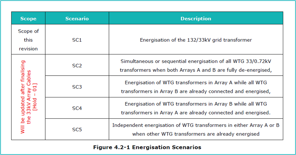
The analysis for SC1 (Study Case No. 1) simulated energisation of the 132/33 kV grid transformer and assessed the resulting voltage disturbance against P28 limits for rapid voltage change. The modelling also considered the interaction between the grid transformer and multiple wind turbine transformers connected to the 33 kV collector system.
Key areas of investigation included:
- Magnetising inrush behaviour of the 132/33 kV grid transformer
- Sympathetic inrush interaction from wind turbine step-up transformers
- Rapid voltage change experienced at the point of connection
- The influence of residual flux within the grid transformer core
- Variation in the switching point on the voltage waveform
Multiple energisation scenarios were assessed to capture both typical switching conditions and worst-case transient behaviour.
To assess the most onerous scenario, all energisations are conducted at the minimum fault level of the point of connection, with various transformer circuit breaker closing times spread across one cycle of the system frequency. The transformer inrush current varies depending on the closing time, resulting in different inrush current values for each timing. To address this, a systematic switching scheme was developed within this study to simulate different switching times and identify the worst-case results.
The following section summarises the energisation results of the 60 MVA grid transformer. A separate engineering article will be issued by EPS to address the energisation of the wind turbine transformers.
Key Findings
Uncontrolled energisation of the 60 MVA grid transformer achieved compliance only under the P28 ‘very infrequent’ event category, permitting a maximum of one energisation event every three calendar months.
The compliance margin was limited and sensitive to residual flux conditions: modelling showed that a residual flux of −0.6 p.u. on Phase B was sufficient to exceed the very infrequent event limit.
Additional sources of uncertainty compounded the magnetisation inrush current issue. A neighbouring substation with a similar transformer was not included in the model – its sympathetic inrush contribution, even if material, could further reduce the compliance margin. The transformer saturation curve used in modelling had not been formally approved by the manufacturer at the time of the study, introducing uncertainty in the inrush characterisation.
The simultaneous energisation of all wind turbine generator transformers was found to be impermissible. Sympathetic inrush effects within each 33 kV collector array drove rapid voltage changes beyond the frequent event envelope when two or more transformers were switched together.
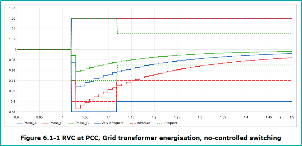


A range of energisation scenarios and mitigation measures are presented and assessed with the aim of controlling grid transformer inrush currents and ensuring compliance with the P28 planning limits as follows:
ENA Engineering Recommendations for Controlling the Grid Transformer Inrush Current
Based on the extensive research and study findings, EPS developed a controlled energisation approach designed to reduce voltage disturbance risk during grid transformer energisation.
Recommended measures included:
- One-Pole Point on Wave (PoW) Switching
- Three-Pole Point on Wave (PoW) Switching
- Transformer De-Magnetisation
1. One-Pole Point on Wave (PoW) Switching
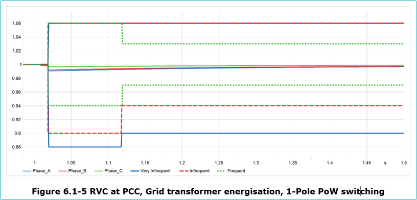
By closing each phase at its optimum point on the voltage waveform, typically close to the voltage peak, the transformer can be energised with minimal core flux imbalance.
Our simulations showed that this approach reduced inrush current significantly, resulting in negligible voltage drop and rapid voltage change at the PCC. Under these conditions, the energisation achieved compliance within the frequent event category.
The main advantage of this method is that it does not depend on residual flux estimation, which makes it a reliable solution where low-disturbance energisation is required. Its limitation is practical rather than technical: it requires a single-pole-operated circuit breaker, which is less common and can be difficult to justify commercially at 132 kV, where three-pole-operated breakers are more typically used.
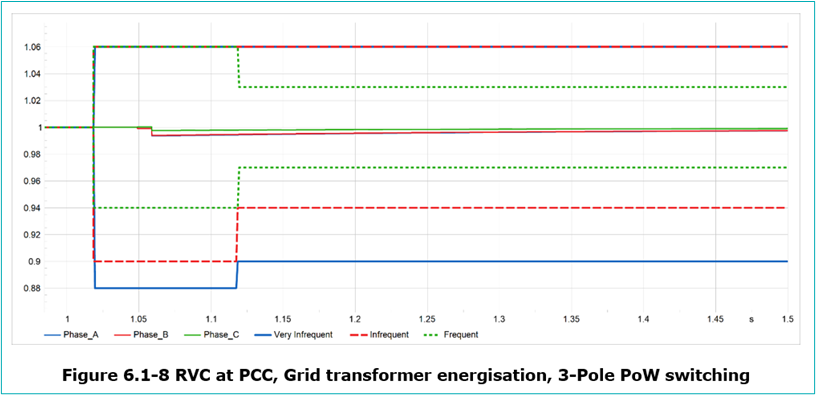
2. Three-Pole Point on Wave (PoW) Switching with Gang Circuit Breaker
Because all three phases close simultaneously, three-pole Point on Wave switching cannot control each phase independently and therefore depends on estimating the transformer residual flux to determine the optimum closing instant.
This introduces more complexity than one-pole switching and creates a greater degree of uncertainty, particularly where factors such as circuit breaker pre-strike may influence switching accuracy and inrush performance. Even so, EPS simulations using the Flux Error Function method showed that three-pole PoW switching could reduce voltage disturbance at the PCC to a negligible level and achieve compliance within the frequent event category.
Three-pole PoW switching is a technically viable mitigation measure where gang-operated circuit breakers are already in use. Any proposed implementation must be supported by proven manufacturer references and validated test results at the same voltage level.


3. Transformer De-Magnetisation
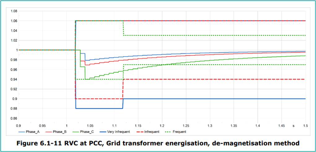
Transformer de-magnetisation provides a further mitigation option where controlled switching is not feasible or is considered too costly. The method works by removing residual flux from the transformer core before energisation using specialist equipment such as the Omicron CPC100.
With the residual flux reduced to zero, the resulting rapid voltage change is significantly lower. EPS simulations showed that this approach could achieve compliance within the infrequent event category, making it a practical way to reduce energisation risk where other switching controls are not available.
It introduces additional operational requirements, including specialist equipment, trained personnel, extra safety procedures, and more time before energisation. If the first energisation attempt is unsuccessful, the de-magnetisation process must also be repeated.
Overall, we consider transformer de-magnetisation a credible and practical alternative where a controlled switching solution is not technically or commercially suitable.
Project Outcome
Without mitigation, the client would have been restricted to one uncontrolled energisation every three calendar months, in the best case, a constraint that would have significantly limited maintenance flexibility and substation availability throughout the project’s operational life. EPS’s assessment removed that constraint by defining a controlled energisation strategy with confidence. The Point on Wave strategy developed by EPS is also applicable to three-pole Point on Wave switching using gang-operated circuit breakers, which are the most commonly used configuration in 132 kV networks.
By identifying risks early, the client was able to plan energisation with confidence, avoiding last-minute mitigation measures that typically add cost and programme risk at the commissioning stage. The outcome also preserved flexibility for future switching operations, avoiding long-term operational constraints that arise when energisation risk is not properly addressed at design.