

Power System Studies for an Existing Electrical Network
Client: Major Water & Wastewater Operator
Location: UK
Services: Power System Studies – Load Flow, Short-Circuit, and Protection Grading Analysis
Date: June 2026
Project Snapshot
The operator plans to add an 815.1 kWp solar PV array at an operational water treatment site.

The proposed works included a new extensible 11kV ring main unit, a 1 MVA PV transformer and future changes to the process transformer arrangement. The new ring main unit would supply both the existing process network and the proposed PV plant.
As the future transformer and 11kV designs were still being developed, the study assessed the proposed arrangement using the latest available design information, while accounting for information gaps to be resolved during the detailed design stage. Where information was unavailable, sound engineering assumptions based on typical industry practice and previous experience were adopted to bridge these gaps.
The Challenge
The existing electrical network had been configured around the site’s established process loads. Adding generation and changing the 11kV arrangement could affect equipment loading, prospective fault levels and protection coordination across the site.
Before progressing the design, the project team needed to establish whether:
- the transformers, cables and switchboards were adequately rated;
- fault currents remained within the capabilities of the existing and proposed equipment; and
- the LV protection system would continue to isolate faults selectively.
The assessment also had to account for the site’s emergency operating arrangement, under which a standby generator supplies essential loads when the normal network infeed is unavailable.
Several inputs could not be confirmed during the non-intrusive site survey. These included some protection device models and settings, cable details, equipment ratings and elements of the upstream HV protection arrangement. The fault-level information to be applied during detailed design also required further confirmation.
Our Approach
EPS developed an ETAP model of the site’s electrical network using the available single-line diagrams, site survey information, design documentation and manufacturers’ data.
The 11kV network was modelled in accordance with the latest issued design, incorporating the existing 800 kVA DNO transformer and the operational LV process network alongside the proposed PV connection.
Three operating scenarios were assessed:
- normal operation with the network infeed and PV plant in service;
- normal operation with the network infeed only; and
- emergency island operation using the standby generator and essential loads.
Assessing each arrangement allowed EPS to account for the changes in network power flow and fault contribution associated with different sources and operating conditions.
Where equipment data or protection settings could not be confirmed, the assumptions were documented, and the affected results were identified for further review. Protection changes were not recommended where the available information was insufficient to support them safely.
Technical Scope
Load Flow Analysis
The load flow study assessed:
- power flows throughout the network;
- busbar and distribution board voltages;
- feeder cable voltage drops;
- transformer loading; and
- equipment loading under each applicable operating condition.
The Adaptive Newton-Raphson calculation method was used, with the PV inverters represented as smart inverters.
Short-Circuit Analysis
Short-circuit currents were calculated in accordance with IEC 60909.
The assessment considered initial symmetrical break current and asymmetrical peak-make current at each relevant busbar. The calculated values were compared with the available switchboard and protective device ratings.
Protection Grading Analysis
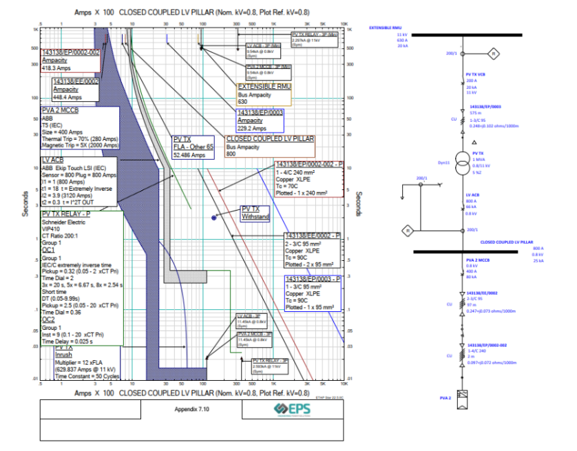
EPS reviewed the LV protection arrangement from the site infeed through to the principal outgoing loads.
Time-current curves and recommended settings were developed for the LV and PV protection devices where sufficient information was available. HV protection evaluation was excluded because the upstream protection device and settings had not been confirmed.
Project Outcome
The studies provided the project team with a clear view of the findings supported by the available design information and the points that still required confirmation.
Load Flow Findings
Busbar voltages remained within the stated limits of +6% and -10% across all three operating scenarios.
The proposed 1 MVA PV transformer reached a maximum loading of 69.4% with the PV plant operating at maximum modelled generation. Voltage drops across the proposed PV cables were also satisfactory.

The study identified that the existing 800 kVA process transformer was operating close to its assumed rating, reaching up to 99.9% loading. EPS recommended repeating the load flow assessment once the rating and specification of the future process transformer had been confirmed.
The incoming cable connected to the secondary of the process transformer was also identified as potentially marginally undersized. Any increase in transformer capacity could require the downstream cables to be reassessed during detailed design.
Several existing feeder cables exceeded or approached the stated 2% voltage-drop limit. Although the corresponding busbar voltages remained within the required range, the results were recorded for consideration as the design developed.
Short-Circuit Study Results
The short-circuit assessment identified that the symmetrical break ratings of Main Pumping Station MCC1 and MCC2 were exceeded in the two normal network-fed scenarios.

The existing intake substation also required further confirmation against the final fault-level information.
These results were based on the 20 kA upstream fault level applied for the assessment. EPS recommended re-evaluating the affected equipment against the confirmed DNO fault level and the final impedance of the proposed process transformer.
Protection Grading Outcome
The LV grading assessment provided recommended settings intended to improve coordination between the site’s protection devices.
However, the existing settings for several devices were unavailable during the survey. The recommendations therefore needed to be checked against the installed site settings and the upstream HV protection before implementation.
No HV protection recommendations were made because the relevant device, transformer information and protection settings had not been confirmed. Without this information, any recommendation could compromise selectivity, sensitivity, and/or equipment protection.
Supporting the Next Stage of Design
The assessment gave the project team a defined set of technical actions before the design progressed further.
These included confirming:
- the future process transformer rating and impedance;
- the applicable DNO fault level;
- the upstream HV protection device and settings;
- outstanding protection device information; and
- the suitability of cables downstream of the process transformer.
This allowed the design team to focus further investigation on the specific parts of the network that could affect equipment selection, protection settings and the final 11kV arrangement.
For an operational water treatment site, identifying these constraints before procurement and commissioning reduces the risk of late changes to transformers, cables, switchboards or protection settings while supporting continuity of supply as the electrical network evolves.
Power System Studies that support a safe connection
EPS carries out load flow, short-circuit and protection grading studies for solar PV and other generation projects connected to operational electrical networks.
Our studies help project teams identify equipment constraints, fault-level issues and protection requirements before they become embedded in the detailed design.